Drop Bar Paddle Remote Install Instructions
Things You Will Need
- Cable cutters, crimping tool
- 2mm, 5mm Hex keys
- T25, T8 Torx keys
- #1 Phillips
- Recommended: SRAM brake barb

COMPLETE EXPLODED VIEW & PARTS LIST
STEP 1: ROUTE CABLE & HOUSING
Before installing the cable into the housing, slide the supplied black cable barrel end onto the cable so that the head of the cable fits snugly in the barrel end.
Route the new cable housing into your frame. When routing the cable housing, avoid tight bends to ensure smooth remote action. Please keep in mind this process will range in difficulty depending on the frame. Care & patience will go a long way.
Route the new cable into the housing, starting at the seat tube end. The barrel end of the cable should be at the seat post side of the housing.


STEP 2: PREPARE SEAT TUBE
Now is the best time to prepare your seat tube. Wipe away any debris or grit from the top and inside of the seat tube. Apply a fresh layer of either carbon paste or a waterproof grease. Both are acceptable.
STEP 3: (V2.1, V3 actuators)
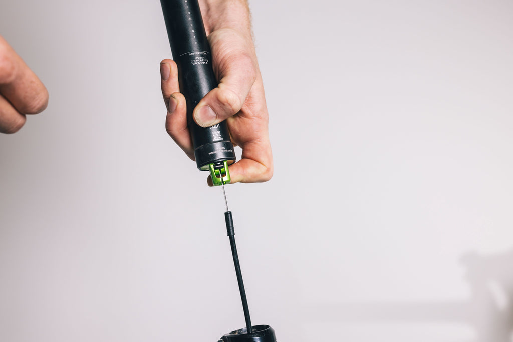
Open the actuator by hand and place the cable barrel into the actuator cradle. Snug the housing into its seat at the bottom of the actuator by pulling on the remote end of the cable.

STEP 4: INSTALL DROPPER TO PEDALING HEIGHT
With the dropper at full extension, install the dropper post to your ideal height in the frame and lightly secure it with the seat clamp. This is best done with two hands. One hand slowly pushes the dropper into the frame while the other hand lightly guides the remote end of the housing out of the frame to avoid the housing bunching & kinking. Avoid yanking on the housing during this process.
STEP 5: SIZE & CUT HOUSING
Once the dropper is at the desired pedaling height, route the housing from where it exits the frame to where the housing ferrule will sit into the shifter/brake body. Mark the housing at an appropriate length prior to trimming it.
Remove the dropper from the frame, reversing the processes in step 4. Once the housing end is exposed out of the seat tube, slide the cable partially out of the housing and trim it at the marked location, then install the ferrule. Slide the cable back through the housing and repeat step 4, remembering to torque the seat collar to 4nm.
STEP 6: BAR TAPE
If the bar is wrapped, fully remove the bar tape from the front shifter/brake side of the bar, this is normally on the left-hand side.
STEP 7: REMOVE SHIFTER/BRAKE FROM BARS
By hand, roll the hood-cover up the shifter/brake assembly. The goal is to expose both the 5mm shifter/brake mounting bolt and the cover plate screws on the side. Using the 5mm hex key, unthread the shifter/brake mounting bolt from the clamp on the bar.

Tip: Slide the hood-cover down and completely off the shifter/ brake assembly, so that it is hanging on the brake cable/hose. This will make the rest of the installation easier.

STEP 8: REMOVE COVER PLATE
Using the #1 Phillips screwdriver, remove the three cover plate screws. Two of the screws are located on the inboard side of the shifter/ brake body, and the third is on top.


Place the screws aside for later. Remove the cover plate and also set it aside for later.

STEP 9: DISCONNECT CABLE
If the shifter/brake body is set up with a front shifter, pull the shift cable out completely.
This step is not required if you have a 1x lever.
STEP 10: REMOVE MOUNTING PIN
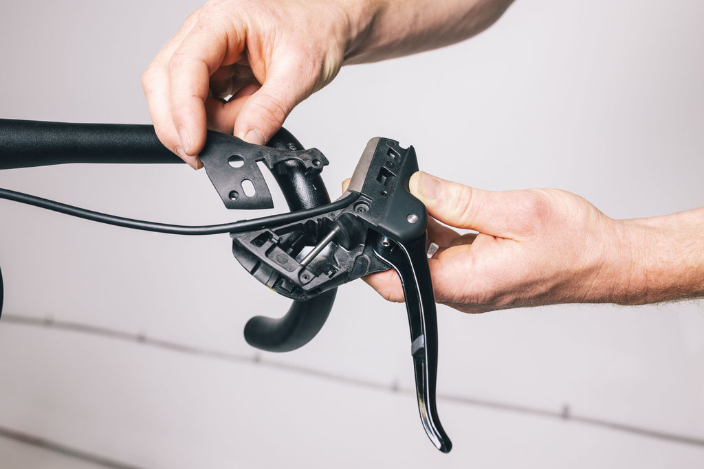
Using the #1 Phillips screwdriver, remove the screw on the outboard side of the lever body that holds the mounting pin into the shifter/brake body. With the screw removed, slide the mounting pin out of the shifter/brake body.

On 1x setups, it should be relatively easy to slide the pin out by hand. 2x setups will require a slightly different technique.
When converting a 2x set up, accessing the pin is a bit tricker. You can use a SRAM hydraulic brake barb and partially thread it into the end of the mounting pin, then use that barb as a handle to pull the pin out. Once the pin is removed, take the shifter lever assembly and set it aside.

STEP 11: INSTALL DROPPER LEVER ASSEMBLY
Remove the packaging twine from the unit. Keeping the two pieces and bushing together, place the tail of the spring into the groove on the shifter/ brake body (see photo for location). Ensure there is tension in the spring (it needs to be pulled clockwise to preload it).

With the tail of the spring sitting in the groove, position the dropper lever assembly so that the mounting rod back into place through the center of the dropper lever assembly. Once it is fully inserted, thread the set screw back into place.


STEP 12: INSTALL & TENSION CABLE
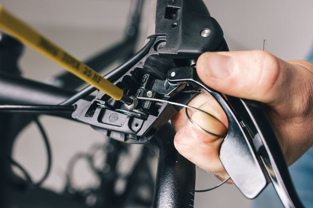
First, pull the cable and housing through the hood cover. Now, pull the cable through the shift cable port in the shifter/ brake body. Ensuring the housing ferrule is snug to its seat, run the cable under & around the set bolt. Using a T25 tool, tighten the bolt down onto the cable. actuate the lever and remove any excess slack in the cable.
If there’s slack in the cable, loosen the T25 cable set bolt, pull the cable taut, and retighten the bolt.

Tip: To reduce the chances of the cable fraying when cut, tighten the set bolt just enough to hold the cable without pinching it. Cut the cable 20mm from the set bolt and crimp the cable end. Now that the cable is cut and crimped, tighten the set bolt fully.

Once the cable has been set, small adjustments can be made using the 2mm hex cable tension adjustment screw. Turning the cable tension screw clockwise will increase tension; turning it counterclockwise will decrease tension.

STEP 13: INSTALL COVER PLATE & HOOD COVER
Fit the cover plate back onto the shifter/brake body. Using your #1 Phillips screwdriver, thread the three screws back into place. Be sure not to over-tighten these screws as they thread into plastic; they just need to snug up, no more.


Before threading it back onto the bar clamp, fit the hood-cover back onto the shifter/brake body. Once the hood is back in place, flip the bottom of the hood up again to expose the 5mm mounting bolt.
STEP 14: POSITION & INSTALL LEVER TO MOUNTIN CLAMP
Thread the shifter/remote body back onto the mounting clamp on the bar using a 5mm hex key.
Tighten until almost snug, then adjust the shifter/brake position to match the other shifter/brake. Once positioned correctly, tighten the mounting bolt. Check both the handlebar and brake/shifter body maximum torque spec prior to final tightening. If they are different, tighten to the lower max torque specification.
STEP 15: CHECK FUNCTION
With the lever tightened to the bar, double check the cable tension and reach position. This step has an element of person preference and will be rider specific.
Cable tension adjustment: You can make small adjustments to cable tension using the 2mm hex cable tension adjustment screw. Turning it clockwise will increase cable tension. Turning it counterclockwise will decrease cable tension.

Reach adjustment: Reach can be adjusted using a 2mm hex screw hiding on the inside at the top of the lever. Turning it clockwise will bring the dropper lever closer to the handlebar and away from the brake lever. Turning it counterclockwise will move it away from the handlebar and closer to the brake lever.

Congratulations, you have completed the OneUp Drop bar remote installation.
You can now wrap the bars and hit the rocky roads!
If you are having any problems, please first double-check that you have correctly followed each of the steps listed.
If you are still having trouble, please fill out our contact form for help. Please include a detailed description of your issue. Photos are often helpful.
Thanks,
OneUp
